Raspberry Pi OBD-II Carputer (obdPi)
June 25, 2016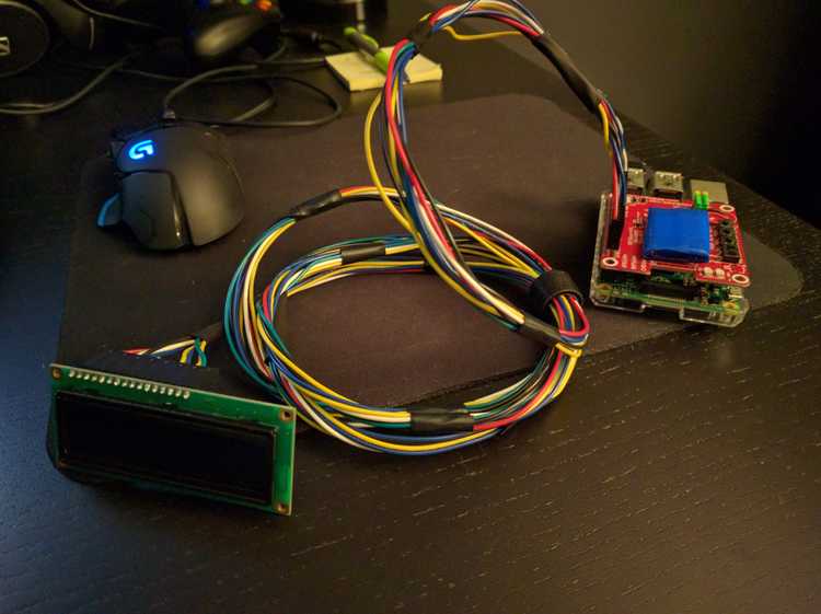
PLEASE NOTE: This blog post is meant to be a conceptual overview of the history of this project. If you are looking for the more technical details on getting your own Raspberry Pi carputer up-and-running, please see the official obdPi documentation here.
Introduction
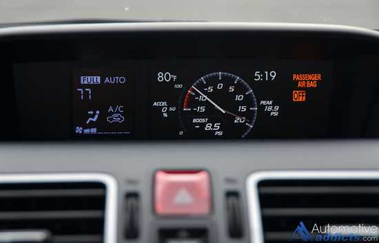
During the summer of 2015, I was looking into boost gauges for my Fiesta ST, and came across a review for the 2016 Subaru WRX. In the video, they mentioned the WRX's central multi-function screen which displays various data like boost, mpg, etc.
Taking inspiration from the WRX and the COBB AccessPort, I got to thinking it would be a great learning experience to build my own boost gauge utilizing a spare Raspberry Pi I had laying around. A rough plan came together, and I figured I'd need to learn:
- How to code in Python
- How to wire a 16x2 OLED display
- How to retrieve OBD-II diagnostic data from my car via Bluetooth
- How to wire a ignition-dependent power supply
- How to configure an extremely lightweight, headless Raspbian OS
With an initial plan in place, I shared my idea with some forums/boards online, and got a number of constructive responses:
Why not use the app Torque Pro? There's already been lots of development on that.
Having installed and messed around with Torque Pro on my phone, I had come to the conlusion that it was a bit "busy" for my personal needs. In addition, I tend to use my phone for calls/music when driving, and my 5" Nexus would obscure a decent amount of my view if mounted to my windshield...
It would be cool if you could interface a pressure transducer to the Raspberry Pi and design a digital display...
Some quick searching revealed a number of projects that did something similar, but (much like the multi-function WRX display) I was looking to pull data beyond just boost pressure. The OBD-II interface provides standardized, straightforward access to a wealth of vehicle data, beyond just boost pressure.
Research
I was able to locate a number of projects online that pursued a similar goal of an in-car computer displaying diagnostic/status data. The first and most well documented was put together by CowFish Studios. Unfortunately, their approach output to a multi-color LCD, and utilized an outdated Python OBD-II library.
Next, I came across CarBerry's quality looking offering. Unfortunately, their system was configured to (again) output to an LCD head unit. In addition, the asking price (including shipping and accessories) was a bit steep for my budget.
There were a couple other projects that appeared either outdated, or lacked any sort of useful documentation, so I decided to just move forward using the best aspects of each of the projects I'd found as an inspiration/guideline.
Supplies
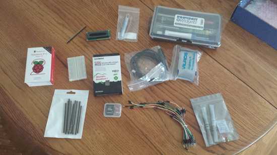
Right around the time I began this project, the Raspberry Pi 2 was just coming to market, so I went ahead and picked up a Vilros Raspberry Pi 2 Ultimate Starter Kit (link is to newer Pi 3 kit). Having never done any sort of electrical wiring before, I figured the kit had (almost) everything I'd need to get started with GPIO wiring the Raspberry Pi.
In addition to the Vilros starter kit, I picked up the following:
- OBD-II Bluetooth Adapter
- USB Bluetooth Adapter
- Soldering Kit (the one I purchased is no longer available)
- Male-to-Female Jumper Cables
- Solderless Large Breadboard
NOTE: If ordering the aforementioned items yourself, don't skimp on a quality OBD-II Bluetooth adapter. The one listed was actually my second, as the first ended up being a cheap knock-off.
Wiring the OLED
After getting the basics of wiring with the Pi down with a few tutorials provided by the starter kit, I decided to jump straight into wiring up an LCD.
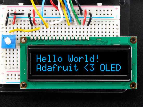
While there are plenty of LCDs available for the Pi, I settled on the Adafruit 16x2 character OLED display for a couple reasons. First, the fact that it's an OLED display means less wiring (no need for a backlight). Second, it's much more readable in direct sunlight. Finally, the display color matches the Fiesta ST gauge screen almost perfectly for that OEM look.
The main downside of this OLED display appeared in the form of little to no wiring documentation online. Adafruit themselves provide great tutorials on hooking up their other LCDs, but support for the OLED display seemed sparse. Feeling brave, I moved forward with wiring everything up using the LCD documentation as a baseline.
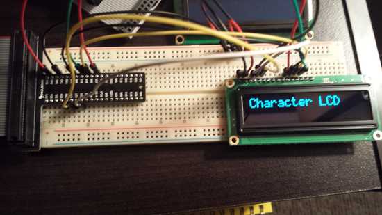
Unfortunately, my first efforts resulted in a fried display. One quick chat with Amazon later, and I had a brand new display shipped for a second try. While waiting for the replacement display to arrive, I ran across a raspberrypi.org forum post concerning wiring the OLED display. Following the suggestions there, I had much better luck the second time around:
For a detailed walk-through and diagrams on wiring an OLED display, please see the obdPi documentation.
Bluetooth and Serial Connections
Now that I had working display, I needed to configure Raspbian to communicate with the Bluetooth OBD-II adapter.
This involved a great deal of trial and error, as I struggled to find much documentation on this specific scenario (Bluetooth OBD-II adapter to Bluetooth USB adapter to Python script in a headless Raspbian installation). However, I was able to get a working configuration together. (See the "Bluetooth Setup" and "Serial Connection" sections of the documentation for more information)
In short, the Bluetooth OBD-II adapter is paired with the Bluetooth USB adapter via the Raspberry Pi's Bluetooth utility. In turn, this Bluetooth connection is mapped to a virtualized serial port, accessible in Python via the pyserial library.
Finally, using entries in the /etc/rc.local startup file, I was able to configure this pairing to run automatically.
Python Scripts
Now that I had a working display and connections, I needed to write some Python scripts to pull the OBD-II data from the car.
I (somewhat optimistically) started at the basics - learning the ins and outs of the OBD-II interface. I had some success...
However, I quickly realized I'd need to find a more elegant solution, as my scripts were rudimentary at best. Thankfully, I discovered the python-OBD library!
In addition to being extremely well organized, python-OBD is consistently being updated with new features, and the author is very responsive to requests/comments/questions.
Leveraging python-OBD, I was quickly up-and-running with a working script, outputting to the OLED display:
As you can see by the flashing display, my code was still far from perfect. However, I was prepared to tackle the next challenge - powering the Raspberry Pi in-car.
Pi Power
I had read mentions of a company called Mausberry in numerous Raspberry Pi tutorials, so I went ahead and order one of their 2A car-based power supplies.
Utilizing a pair of 12V sources (one dependent on the ignition, one always-on), the Mausberry car switches are designed to provide power to the Raspberry Pi when the car is switched on, and send a "safe shutdown" command when the ignition cuts power. In theory, these switches appeared to be perfect solution for this project.
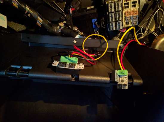
Unfortunately, after ordering and installing one of their car switches, I quickly ran into issues. I had wired the switch into my car's fuse box using a pair of fuse taps:
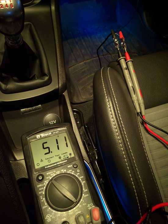
Initial testing seemed to suggest the switch was working perfectly. However, after approximately 30 seconds of power, the switch would cut all power to the Pi forcing it to shutdown. I ended up testing a number of different fuse combinations, wires, USB cables, and even wiring it directly to the car's battery with to no avail. After cannibalizing a USB cable, I hooked up a multimeter and found that the Mausberry switch itself appeared to be the issue.
I reached out to Mausberry but after weeks of waiting, had received no response. Giving the benefit of the doubt, I went ahead and ordered a second switch. After a nervous period with no word on my order, I received the new switch (this time the 3A offering) in the mail a few weeks later.
However, testing with the new switch seemed to suggest it was suffering from the same issues. I once again tried a variety of cables, power sources, and fuses with no success.
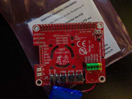
At this point, I was fairly frustrated and frankly fed up with the lack of communication on Mausberry's part. Fortunately, I came across an alternative solution in the form of the UPS PIco from Pimodules. I reached out directly to Pimodules, asking if the UPS would be suitable in a car application. They replied almost instantaneously affirming their confidence that it would, so I went ahead and ordered one!
Thanks to customs and international shipping, it took a while to arrive. But upon initial inspection, I was thoroughly impressed.
The set up guide was extremely well written and easy to follow.
In short, the UPS utilizes a small 450mAh LiPo battery to provide power to the Pi if a loss is detected (i.e. the car is shutdown). It then uses a few scripts to trigger a safe shutdown after a few seconds of power from the battery. The UPS also provides the option to add a cooling fan, as well as providing easy access to voltage information, battery level, etc. In addition, the UPS's status LEDs help distinguish when the UPS is running off of the 5V or battery power at a glance.
As a result of the excellent documentation, I had the UPS configured and working perfectly in less than an hour. Needless to say, after months of frustration and waiting, I had a fully functional system ready for installation in the car!
To the Car!
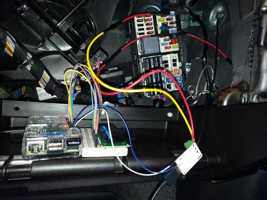
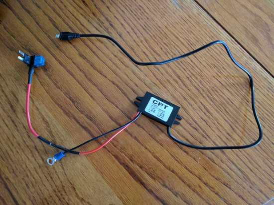
Since I would no longer be utilizing the Mausberry circuit's built-in voltage converter, I had to find an alternative solution for stepping the 12V power source from the car down to a more Pi-friendly 5V. I found this regulator on Amazon, and wired everything up:
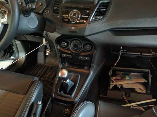
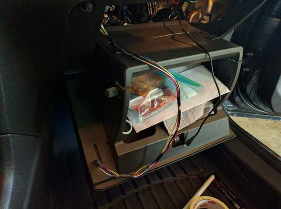
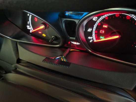
With everything ready to go, I first threaded the OLED cable through the dash from the glovebox:
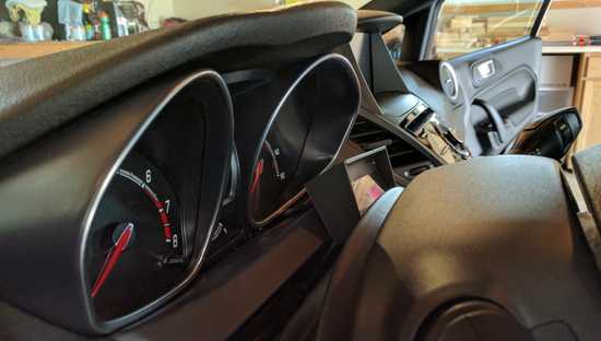
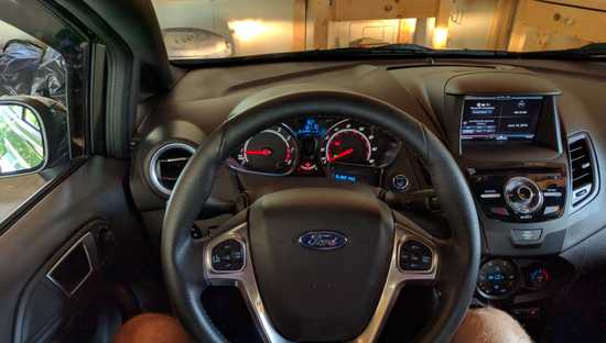
I decided to position the OLED display just beneath the gauges - this seemed simplest with regards to getting the cable through everything.
Finally, it was time for a test drive!
HALLELUJAH! With the entire system working as intended, I left it installed for a few weeks of testing and, while there are certainly a few bugs to work out, ran into no major issues!
OLED Housing
With the hard work done, I decided to tackle the last "piece of the puzzle" per say.
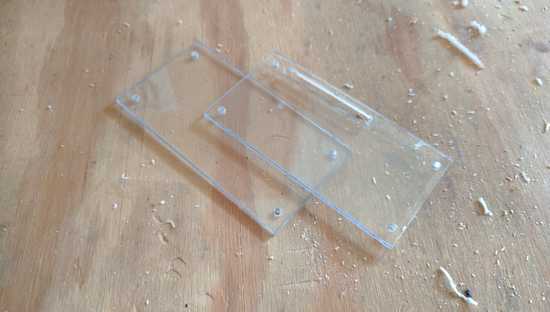
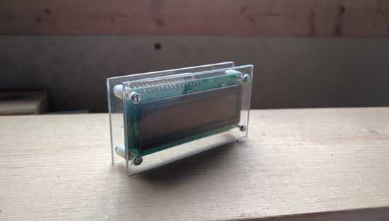
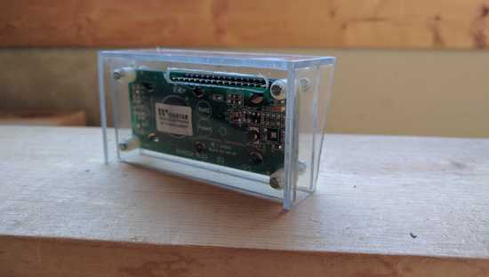
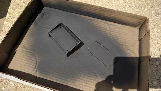
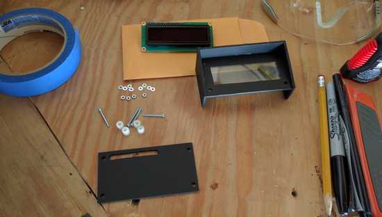
The visiblity of the green OLED PCB against the black of the car's dashboard was fairly uninpsiring, so I decided to throw together a simple little housing for it out of some perspex plastic I picked up from Home Depot. (Plus it was an excuse to finally buy a Dremel...)
What's Next
This entire experience has been a great lesson. What started as an afternoon brainstorm eventually became one of the most frustrating and time-consuming projects I've ever worked on. There were many late nights in the garage (both freezing and baking-hot), on my laptop, cursing Python and thinking it was a lot harder than it should be.
A special shout-out to my girlfriend specifically, for her patience and understanding - never asking questions as to why I was carrying piles of electronics and wires around the house (she did mention something about "making a bomb" once), but always being there to motivate and encourage me.
To some, it may seem trivial or "simple". But to me, it's become a lesson in not only patience, but a testament to the benefit of sticking with a project - no matter how many times you might fail. Because the end results are always worth it.
I'm very excited for the future of this project, and I'm already putting together a huge list of "to-dos".
Thanks for reading!

