Arduino OBD-II Carputer
November 18, 2017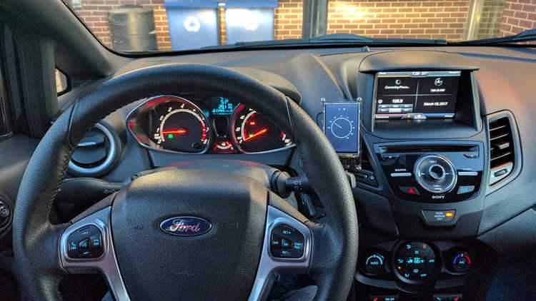
When I published my Raspberry Pi OBD-II Carputer project a little over a year ago, I could never have expected the overwhelmingly positive response it received.
Through dozens of comments, emails, and even a few in-person discussions at tech conferences, I began to realize there's a much larger market for OBD-II and Raspberry Pi than I first thought. Most recently, at That Conference in the Wisconsin Dells, I attended a few talks on hacking OBD-II. Through those sessions, I was able to network with a couple of awesome people who were just as excited about the possibilites of OBD-II + Pi as I am!
Unfortunately, following my original post last June, development on the obdPi project fizzled out. I quickly realized there were a number of important limitations when considering the Raspberry Pi as a carputer, specifically boot time and power management.
Raspberry Pi Limitations
The main issue with my original obdPi approach is the time required to boot the system when the vehicle is powered on.
From a cold start, my best effort bare-bones Raspbian image takes around 20-30 seconds to fully boot. Due to the many systems and utilities needed to power the obdPi system (Bluetooth, OLED, wireless, etc.), I've struggled to find a way to cut down this boot time. I've even looked into simulated standby hardware (such as Sleepy Pi), but this still relies on the Pi actually booting quickly.
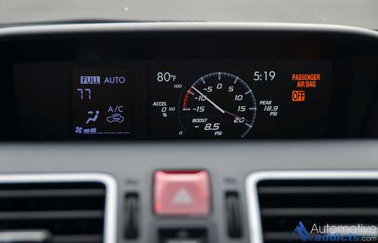
The more I thought about the problem, the more I realized the Pi might be overkill for the type of functionality I was trying to achieve. You see, my original goal was to simply replicate the real-time performance monitoring functionality of the Subaru WRX's multifunction display.
With a bit more research, I discovered a great community supporting the Arduino platform. I dug a bit deeper, and almost immediately the Arduino became an appealing alternative to the Pi; specifically for its simplicity and near-instantaneous boot time.
Pi vs. Arduino
When comparing the Pi to the Arduino, they each have their own strengths/weaknesses.
Simply put, the Pi is designed to support a full operating system, but lacks built-in sensors and requires a constant, stable power supply. On the other hand, the Arduino's strengths include simplicity, extensibility, and incredibly fast boot times. However, the Arduino lacks the raw power and multi-tasking ability of the Pi.
In the case of obdPi, the ability to extend the functionality of the system beyond basic performance monitoring has always been an appealing option. However, considering the tradeoff of longer boot times (a major factor in a carputer), the Arudino certainly seemed to fit my needs much better.
Exploring Arduino Options
I decided to start by ordering up an Arduino Uno R3 from Amazon. With nothing more than a basic USB 2.0 cable and the Arduino IDE on my laptop, I had the little Uno up and running in no time.
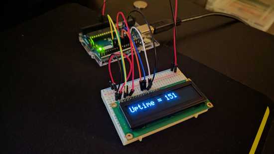
I was immediately impressed with how easy to use the Arduino platform is. Coming from the (often) "trial and error" world of Raspberry Pi, the simplicity of Arduino's IDE and clear, concise tutorials were a breath of fresh air. In minutes I had a few basic sketches running, and even getting my obdPi 16x2 OLED connected!
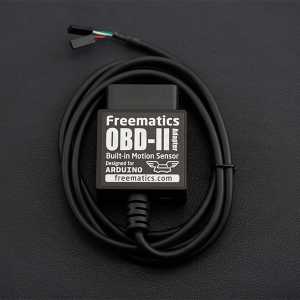
As I started researching existing Arduino OBD-II projects, I came across Freematics - a homebrew company that specializes in OBD-II Arduino hardware. While they offer a number of wired and wireless adapters for OBD-II, I decided to order up one of their V2 UART Adapters.
Freematics Makes It Easy
Utilizing nothing more than the OBD-II interface, the V2 adapter provides a single cable solution for both power and OBD-II data. Out of the box, it's designed to work with Freematics' ArduinoOBD library.
A basic sketch is as simple as:
#include <Wire.h>
#include <OBD.h>

COBDI2C obd;

void setup()
{
  // we'll use the debug LED as output
  pinMode(13, OUTPUT);
  // start communication with OBD-II adapter
  obd.begin();
  // initiate OBD-II connection until success
  while (!obd.init());
}

void loop()
{
  int value;
  // save engine RPM in variable 'value', return true on success
  if (obd.read(PID_RPM, value)) {
    // light on LED on Arduino board when the RPM exceeds 3000
    digitalWrite(13, value > 3000 ? HIGH : LOW);
  }
}
As you can see, this is loads easier than configuring a Bluetooth OBD-II connection on the Pi. Plus, having a single cable doing everything is just icing on the cake.
With the easy stuff out of the way, I knew it would be necessary to implement some sort of external display. Initially I considered re-using the 16x2 OLED from the obdPi project, but realized that would require a whole extra set of cabling to be routed somewhere in the car.
Getting in Touch
I pulled back up Freematics' site and noticed they offer a 3.5" Touch LCD Shield for the Arduino Mega:
Built by DFRobot, this shield is designed to seamlessly integrate with the V2 UART cable; with the necessary male connectors conveniently pre-wired at the base of the display; perfect for my project, so I ordered one up!
While waiting for the LCD to ship, I headed over to my local Microcenter and picked up one of their generic brand Arduino Megas. (Amazon also stocks Megas)
NOTE: You can also order the LCD Shield + Mega + V2 Cable as a kit from Freematics, but I found it a bit cheaper to buy the Mega separately.
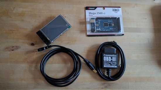
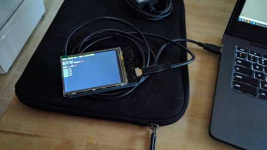
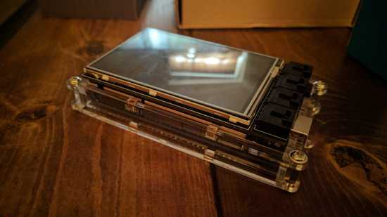
Once the LCD shield arrived, I put everything together:
Thanks to a few sample sketches on the Freematics Github, I was up and running in no time!
Freematics had done pretty much all the heavy lifting at this point, and I had a fully functional Arduino OBD-II performance monitor ready for use in the car. Rather than stop there, however, I decided to dig deeper into the Freematics code and figure out if I could hack the display into a cooler GUI-based layout.
COBB Accessport
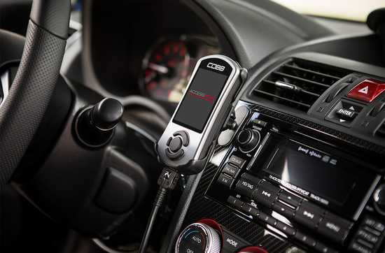
With obdPi, my original intentions had been to eventually integrate the entire system into my car's dashboard. However, thanks to the Freematics LCD shield, I realized there was an opportunity to develop a standalone performance monitor similar to COBB Tuning's Accessport.
For those of you who don't know, the Accessport is the go-to device for anyone looking to tune their vehicle's ECU. Currently on it's third revision, the Accessport (or AP) is designed as an easy way for owners to upload, manage, and monitor various tunes and performance maps for their vehicle. Much like rooting or jailbreaking an Android or iOS device, cracking a vehicle's ECU provides the opportunity to optimize various parameters for increased performance and/or efficiency. In addition, the Accessport offers real-time performance monitoring and logging.
While I'm not brave enough to dabble in the dark art of ECU tuning myself, I do see the appeal of having access to real-time performance data, as well as the ability to log this data for later reference. As such, I decided to take a stab at replicating Accessport-like functionality using my Arduino setup.
Having already sorted the hardware side of things, I turned my attention to the software. While Freematics' Arduino libraries already provide a variety of performance data, I wasn't satisfied with the basic layout and GUI.
Gettin' GUI With It
I started by dissecting the example scripts from Freematics' Github repo, and quickly realized there was a bunch of extraneous code in a number of the libraries (for my purposes). In addition, while there seemed to be a solid foundation for extended functionality, the original code didn't easily allow for things like a rotated screen or a page-based layout.
As a result, I spent a good amount of time refactoring and optimizing the base libraries. After successfully rendering a portrait-oriented design on-screen, I moved on to building the various gauges and menus I envisioned.
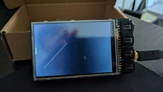
Things moved pretty slow at first...
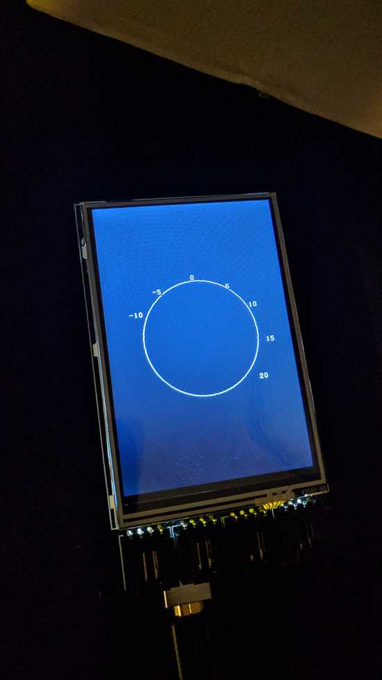
But I quickly built an appreciation for the programmers in the early days of GUI interfaces. After some trial and error, I was able to generate rotating gauges. Determining the endpoints and positioning of the various lines, labels, and other shapes had me racking my brain for middle school geometry equations (see kids - you do use that stuff eventually) and turned out to be a lot more fun than I thought it'd be!
In the end, I had a few working gauges and had gotten the touch functionality working (a simple screen tap would cycle through the gauges). At this point, I was ready to test everything out in the car, but still hadn't settled on a good mounting system.
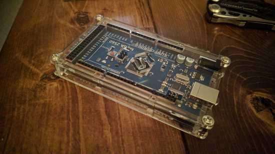
Taking some inspiration from the Accessport, I found a case for the Arduino Mega that would allow enough clearance for the LCD shield. The SunFounder Mega 2560 on Amazon looked like it'd fit the bill.
The case fit perfectly, and with the pin headers left exposed and flush with the outside of the case, I was able to re-install the LCD shield with no issues!
With the case sorted, I decided to utilize an Anker air vent magnetic phone mount for mounting the Arduino in the car. This would allow me to reposiiton the Arduino as many times as I like, and thanks to the new case, I had a surface on which I could safely mount one of the adhesive magnetic patches.
Moar Power!
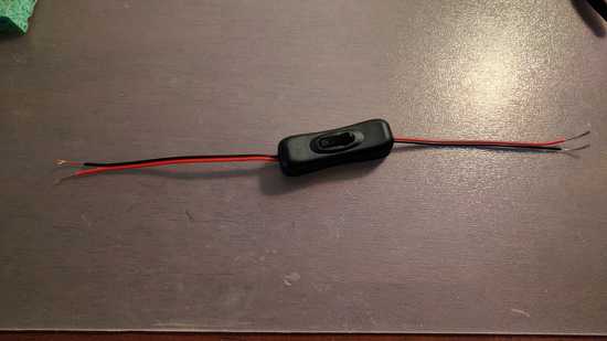
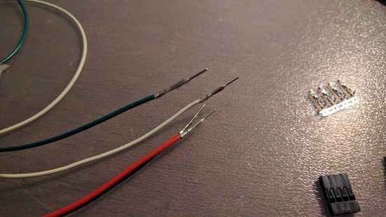
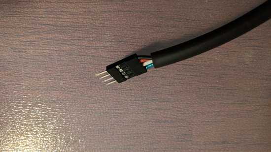
Because the Freematics adapter utilizes the OBD-II 12V pin to power the Arduino (a constant 12V source), I needed to figure out how I could power the Arduino off when the car turned off. After considering a few software options, I decided to build an inline hardware kill switch. I ordered a few LED inline power switches, chopped the ends off, added a pair of additional wires (to extend the Freematics data lines) and terminated both ends in matching male/female 1x4 connector housings.
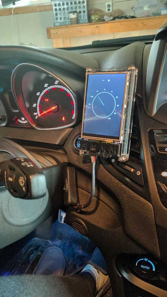
Killswitch sorted, I was ready to install everything in the car. Thanks to the single cable of the Freematics adapter, it was easy to run everything up the dash and out the side of the steering column. I wired in the killswitch and installed the Arduino on the magnetic Anker mount, then fired everything up for a test run.
In the video you can see the working boost and RPM gauges! Needless to say I was amazed and excited I had gotten this far. The only thing left to do was clean up the code and add a few more gauges!
Work in Progress
Unfortunately, life happened (we moved houses) and I was forced to sideline the project for a number of months. By the time I got the time and inspiration to pick the project back up, I found myself in a position to sell my Fiesta ST and move up to a Subaru WRX - the car that started this whole carputer thing in the first place. While I cover that experience in detail over on my other blog, I realized I was moving into a car with the kind of functionality and gauges I had been hacking together in my free time in the months prior. This made me a little sad, as I realized I no longer had a need for the Arduino carputer.
It's been a few months since buying the WRX, and I still haven't had the opportunity to pick this project back up. However, I did want to share my experience with you so I've published my working code on my Github here.
Maybe one day I'll find a new use for the Arduino carputer, but for now I'm enjoying the car as-is way too much. I hope this project can inspire someone else, and hopefully this post/code helps in some way. If you are interested in the project and have questions/want to chat, please don't hesitate to shoot me an email! I'd love to see what you're working on!

